The M1H User Manual Outlines A Sophisticated Vehicle Loop Detector Designed For Reliable Traffic Management And Access Control Systems. This Device Functions As A Critical Component In Detecting The Presence Or Passage Of Vehicles Through Inductive Loops. Understanding Its Nuanced Settings, Wiring Configurations And Diagnostic Indicators Is Essential For Optimal Deployment In Environments Such As Parking Lots, Toll Booths And Automated Gates.
The M1H Detector Is Engineered With Versatility In Mind. Its Primary Function Is To Detect Metal Objects (Vehicles) Entering An Inductive Loop. The Device Boasts Several Key Features That Enhance Its Utility. First, It Employs A Self‑Detection Mechanism. Whenever The DIP Switch Is Toggled Or The Presence Output Time Is Modified, The System Automatically Initiates A Self‑Diagnostic Routine To Ensure Calibration Matches The Environmental Conditions.
The Physical Design Includes An ABS Alignment Structure, Allowing The Unit To Be Mounted Compactly Alongside Pillars Or Within Standard Housings. Crucially, The M1H Offers Adjustable Presence Output Time And Work Modes, Which Can Be User‑Configured Via DIP Switches. It Supports Both Pulse And Permanent Output Signals, Making It Adaptable To Various Gate Controllers And Barrier Logic Requirements. The Manual Also Notes The Ability To Change The Loop's Work Frequency To Avoid Cross‑Talk With Adjacent Loops Or Environmental Interference, A Vital Feature In Multi‑Lane Installations.
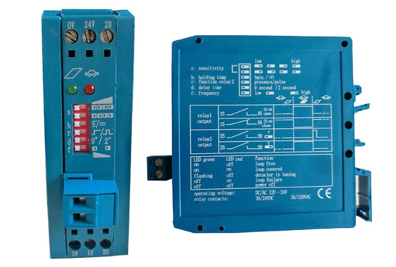
The Links Diagram Provided In The Manual Illustrates The Standard Wiring Topology. The Detector Operates On A Power Supply Ranging From AC/DC 12 To 24 Volts. The Wiring Harness Connects The Loop Terminals, Power Inputs And Relay Outputs.
There Are Two Distinct Relay Outputs (Relay 1 And Relay 2). Relay 1 Is Typically Configured For The Primary Detection Logic, Often Controlling The Barrier Gate Or Access System. Relay 2 Can Be Configured As A Secondary Output, Often Used For Signaling Specific States Like "Presence" Or "Pulse."
A Critical Aspect Of The Wiring Is The Jumper Wire Configuration. The Manual Specifies That When The Jumper Wire Is Open (Not Connected), The Output Logic Is "Normally Open" (NO). In This State, The Relay Pins Remain Disconnected (Open) When The Vehicle Is Absent. When A Vehicle Enters The Loop, The Two Pins Pull Into Conduction (Close The Circuit), Activating The Output. Conversely, When The Jumper Wire Is Connected To The "Close" End, The Logic Reverses To "Normally Closed" (NC). This Means The Pins Are Pulled In (Conducting) By Default When No Vehicle Is Present And Disconnect When A Vehicle Enters The Loop.
Furthermore, The Function Of The Output Pins Varies. The Manual Highlights That The "Pulse" Mode On Pin 25 Or 28 Is Dictated By DIP 4. If DIP 4 Is Set To The OFF Position, The Output Acts As A Pulse; When The Vehicle Leaves The Loop, The Relay Disconnects After A 1‑Second Pull‑In. If DIP 4 Is Set To The ON Position, The Two Pins Pull In After The Vehicle Passes The Loop, Providing A Trailing Pulse Rather Than A Leading Pulse.
Proper Calibration Is Vital For Avoiding False Detections Or Missed Vehicles. The M1H Provides Four Levels Of Sensitivity, Adjustable Via DIP Switches 1 And 2 On The Front Panel. These Settings Are Labeled "Higher," "High," "Low," And "Lower." The Manual Advises That If A Vehicle Fails To Trigger A Response During Testing, The Sensitivity Should Be Improved. High Sensitivity Is Typically Used For Small Vehicles Or When The Loop Is Physically Small, While Lower Sensitivity Helps Prevent Interference From Adjacent Loops Or Environmental Noise.
Frequency Adjustment Is Another Layer Of Protection Against Interference. The Device Offers Two Frequency Styles Controlled By DIP 6. By Selecting Different Frequencies On Adjacent Loops, Installers Can Minimize The Risk Of "Cross‑Talk," Where The Magnetic Field Of One Loop Interferes With The Detector Of Another. This Is Particularly Important In High‑Density Parking Areas.
The Concept Of "Presence Time" Refers To How Long The Detector Maintains The Output Signal After The Vehicle Has Stopped. This Is Controlled By DIP 3. The Manual Defines Two Distinct Modes.
When DIP 3 Is Set To The OFF Position, The Presence Time Is Limited. Specifically, The Detector Holds The Signal For Up To 5 Minutes. If A Vehicle Remains On The Loop For Longer Than This Duration, The Detector Assumes The Vehicle Has Left Or That There Is A Fault, And It Automatically Resets To The "Carless" Condition. This Prevents A Stuck Output That Could Paralyze A Gate System.
Conversely, When DIP 3 Is Set To The ON Position, The Presence Time Is Unlimited. This Means As Long As The Vehicle Is Physically On The Loop, The Detector Will Maintain The Output Signal Indefinitely. This Mode Is Often Used For Fail‑Safe Applications Where The Gate Must Not Close Under Any Circumstance While The Vehicle Is Present.
Additionally, DIP 5 Controls The Signal Output Behavior Regarding Delay. Setting DIP 5 To OFF Results In An Immediate Signal Output As Soon As The Vehicle Enters The Loop. Setting DIP 5 To ON Introduces A Delay, Causing The Signal To Be Output Only After The Vehicle Has Been Present For Two Seconds. This Delayed Output Can Be Useful To Prevent False Triggers From Quick Movements Near The Loop Edge Or Passing Pedestrians.
The M1H Features A Dual LED Indicator System (Green And Red) That Provides Real‑Time Status Updates.
During Power‑Up, Both LEDs Play A Role In The Self‑Calibration Process. The Green LED Will Flash, And The Red LED Extinguishes. During This 1‑Second Phase, It Is Critical That No Vehicles Are On The Loop, As The Detector Is Establishing A Baseline. If A Vehicle Is On The Loop During This Time, The Calibration Will Be Incorrect.
Once Calibration Is Complete, The Green LED Stops Flashing And The Red LED Remains Extinguished, Indicating The Detector Is Ready For Operation. When A Vehicle Enters The Working Condition, The Red LED Turns On. If The Red LED Is On And The Green Is Off, It Indicates The Vehicle Is Currently Detected. The Manual Also Notes A Diagnostic State Where The Green LED Is Off And The Red Is On, Which Indicates The Detector "Can Not Detect The Loops"—Likely Indicating A Fault With The Loop Wire, Such As A Short Circuit Or Break.
To Ensure Longevity And Compatibility, Installers Must Adhere To The Technical Specifications. The M1H Operates On A Power Supply Of AC/DC 12‑24V. The Output Relay Is Rated For 120V/3A AC, Capable Of Handling Standard Gate Control Voltages. The Operating Temperature Range Is Robust, Spanning From ‑20°C To +70°C, Making It Suitable For Outdoor Installations In Varied Climates.
The Device Supports A Loop Inductance Range Of 50 To 800 Microhenries (uH), Though It Is Optimized For 100 To 300 uH. The Work Frequency Ranges Between 20 And 130 KHz. Physically, The Unit Is Compact, Measuring 79mm By 22.5mm By 90mm, Allowing It To Fit Into Standard Control Boxes.
In Summary, The M1H User Manual Describes A Highly Configurable And Resilient Vehicle Detection Solution. From The Ability To Reverse Relay Logic Via Jumpers To The Granular Control Over Sensitivity And Presence Timing, The M1H Provides The Flexibility Required For Modern Traffic Control Systems. Proper Attention To DIP Switch Settings And LED Diagnostics Ensures A Stable And Efficient Installation.
 Hot News
2026-03-11
Copyright © 2026 Chisung Intelligence Technology (Shenzhen) Co., Limited All rights reserved. - Privacy policy
 EN
EN