Automatic Sliding Door Opener: Comprehensive Installation and Technical Guide
I.Critical Safety and Installation Prerequisites
The installation of the X9 automatic Sliding door system is a specialized task that must be undertaken with the utmost care and adherence to safety protocols. The manual explicitly states that installation must be entrusted to appointed distributors or professional installation personnel. Failure to comply with this directive not only poses significant safety risks but may also violate local laws and regulations. This manual serves as the definitive guide for installation, adjustment and maintenance, and it must be kept in a safe place for future reference.
The manual utilizes a series of graphical symbols to convey mandatory actions and prohibitions. A key warning indicates that careless installation and adjustment can lead to severe accidents, including fire, electric shocks or the door falling off its track. During the installation process, it is imperative to prevent pedestrians from passing through or approaching the work area, as falling tools or parts could cause serious injury. Modifying any part of the system is strictly forbidden, as this could also lead to fire, electric shock or failure. The system must be operated exclusively within its stipulated voltage and frequency parameters to prevent electrical hazards.
Special emphasis is placed on the correct setup of safety sensors. The sensor must be adjusted to ensure the entire opening area of the door is within its detection range, with no blind spots. An improperly adjusted sensor could lead to pedestrians being struck or caught by the moving door leaf. Similarly, the installation of a photocell is mandatory to monitor the walking area of the door leaf, providing an additional layer of protection against collisions. Operational environments must be free from excessive dampness, vibration or corrosive gases. Users must also ensure a minimum clearance of 30mm when the door is opened to prevent fingers from being trapped between the door leaf and the frame.
II.Technical Specifications and Components
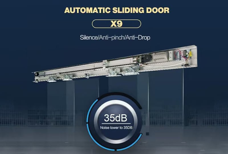
The X9 model is a sophisticated automatic sliding door system that integrates advanced microprocessor control technology with precision mechanical manufacturing. It features a brushless DC motor, which is highlighted for its long service life and low noise output, operating at less than 40 decibels. The system is designed with a self-learning function upon power-on, a feature that can be enabled or disabled by the user. A digital screen provides precise and easy adjustment of all operating parameters. The system includes functions for anti-clamping during both closing and opening cycles, and it offers dedicated terminals for a variety of accessories, including electronic locks, access keypads, function keypads, remote controls and anti-clamp side sensors for enhanced safety.
The technical specifications provide the operational limits of the system. For a single-opening configuration, the X9 can support a maximum door leaf weight of 130 kg. In a double-opening configuration, it supports two leaves with a maximum combined weight of 240 kg (2 x 120 kg). The permissible door leaf width ranges from 700 to 1300 mm for single openings and 600 to 1250 mm for double openings. The system is powered by a universal AC 90–250V 50–60Hz power supply. Both the opening and closing speeds are adjustable within a range of 15 to 55 cm/s. The hold-open time is also adjustable, from 0 to 20 seconds. The manual open force is specified as less than 40N for a single leaf and less than 50N for double leaves, with the motor operating at 24V, 50W, and 2800rpm. The system is designed to function reliably in ambient temperatures ranging from -10℃ to +70℃.
III. Installation of Mechanical Components
The installation process is a systematic procedure that begins with preparing the main aluminum track. The standard track length is 4200 mm and the required length (L) is calculated by subtracting 10 mm from the total door width (W). The track must be installed level at a height of DH+23mm from the finished floor level (where DH is the height of the movable door leaf). After drilling the necessary holes, one end of the track is fixed, and the level is checked before securing the other end to the steel structure firmly.
The motor, controller and idler pulley are installed by inserting their respective mounting plates into the upper and lower grooves of the track. For the motor, the lead wire with a connector must be routed correctly to prevent it from being dragged. The controller is inserted similarly and its mounting bolts are tightened. The idler pulley is temporarily fixed in a position that allows for slight movement to facilitate belt tensioning later. The manual stresses that misoperation during these insertion steps can result in the unit falling off the track. Stoppers are installed after determining the open and close positions to limit the door's travel. The hangers are attached to the door leaves and the anti-drop device is then fitted to prevent the door from derailing. Care must be taken to ensure the hanger pulley center is parallel to the door leaf to prolong its service life.
Door leaf installation and adjustment are critical for smooth operation. For single and double openings, the height of the door leaves can be adjusted using an adjusting bolt on the hanger; turning it clockwise raises the door and counterclockwise lowers it. After adjustment, a 0.5mm gap must be maintained between the rail and the anti-drop device. The installer must then confirm the door operates with minimal resistance by checking for friction between the hanger and rail, the floor guide or the door frame.
IV.Belt Installation and Tensioning
The timing belt is a crucial component for transmitting power from the motor to the door leaves. The installation process involves removing the belt fastening part, cutting the belt to the correct length as per the provided belt cutting table, ensuring the cut is made at the center of the belt's valley bottom. The ends of the belt are inserted into the fastening part and secured to the belt connector, with caution to avoid twisting the belt. The manual provides specific installation positions for the belt fastener for both single-leaf and double-leaf configurations. A belt length table is included for reference, correlating door width to the required belt length.
Proper belt tension is essential for reliable operation. After installation, the tension is adjusted at the idler pulley. This process involves loosening the fastening bolts, using the tension adjusting bolt to position the plate and then tightening the belt by adjusting the bolt. The belt should be tensioned suitably—not too tight to cause excessive wear, nor too loose to cause slipping. The manual notes that the belt will stretch over time and will require periodic readjustment by repeating this procedure.
V.Electrical Connections and System Configuration
All electrical connections must be performed with the power off to prevent electric shock and damage to the controller. The manual provides detailed diagrams and terminal details for connecting various accessories. The sensor, which is essential for automatic operation and safety, should be installed at the center of the door leaf, with a maximum installation height of 3 meters. The electronic lock is installed with a dedicated bracket and magnet holder, with a specified gap of no more than 5mm between them when the door is closed. Terminals are provided for connecting access keypads, interlock systems and photocells, all with positive and negative polarity considerations.
The controller features a detailed terminal block. Notable connections include terminals for the photocell input, access keypad, interlock input and output, a +12V power supply for accessories and a +24V UPS input for battery backup. The lock control terminal provides a +12V output. A dedicated 12-16 terminal is for a remote control receiver.
The adjustment of open and close parameters is performed using a series of knobs and switches on the controller. The manual describes the function of each component, including the TEST button for verifying adjustments and the DRP indicator. Key adjustable parameters are labeled A through I and include:
(A) Left/Right Switch: Determines the opening direction.
(B) Toggle/Normal Switch: In "Toggle" mode, the door remains open until a new signal is received.
(C) Backup Battery Mode: Configures the door's behavior when running on battery power.
(D) Opening Speed: Adjusts the speed of the opening cycle.
(E) Opening Buffer Distance: Adjusts the point at which the door decelerates before the fully open position.
(F) Closing Speed: Adjusts the speed of the closing cycle.
(G) Closing Buffer Distance: Adjusts the point at which the door decelerates before the fully closed position.
(H) Buffer Speed: Adjusts the speed of the deceleration itself.
(I) Hold Open Time: Adjusts how long the door remains fully open before automatically closing.
A systematic adjustment process is recommended: manually check for smooth operation, set the toggle/normal switch and direction, set preliminary parameters with a long buffer distance to prevent crashing, and then power on and fine-tune the closing parameters before adjusting the opening parameters.
VI.Troubleshooting Guide
The manual includes a comprehensive troubleshooting section to assist with common issues. For instance, if the door opens or closes unsmoothly, potential causes include incorrect speed settings, mechanical resistance from hangers or guides or obstacles on the track. Remedies involve adjusting the speed settings on the controller, fixing loose components, and cleaning the track. If door leaves hit each other when closing, the cause could be a loose stopper or an inappropriate combination of high closing speed and a short buffer distance. The remedy is to fix the stopper correctly or adjust the closing speed and buffer distance parameters.
If the door does not work at all, the manual guides the user to check for no power input, a blown fuse, a locked door, poor motor-controller connections or an active interlock system. For a door that fails to close, the diagnostics include a constantly triggered sensor or photocell or an active "always open" function. Causes for a door that opens by itself include sensor interference from fluorescent lights or strong microwave machines or simply dirt in the detection area. The manual provides clear steps for each issue, such as cleaning the sensor surface, realigning the photocell receiver and emitter or moving sources of interference away from the sensor.


 Hot News
 EN
EN