Comprehensive Overview of the CSSMFDO-01 Side-Mounted Flat Door Opener
The CSSMFDO-01 Side-Mounted Flat Swing Door Opener represents a significant advancement in the automation of modern swing doors. Engineered by a specialized manufacturer, this intelligent device integrates sophisticated microcomputer chip technology with digital control systems. The primary goal of this design is to deliver a product that is not only powerful and reliable but also exceptionally safe and user-friendly, streamlining both the installation process and subsequent operational adjustments. Before delving into the technical specifications or installation procedures, it is imperative for the end-user and installer to thoroughly familiarize themselves with this operation manual. This careful preparation ensures the device can be utilized to its fullest potential, guaranteeing both longevity and optimal performance.
一、Operational Workflow and Core Features
The operational logic of the door opener follows a structured and intelligent sequence to ensure smooth and secure door movement. The main process is composed of several distinct phases: Opening, Opening Buffer, Holding, Closing, Closing Buffer and finally Locking. This detailed workflow is triggered by an opening signal from an external device, such as an access control system or a manual switch. Upon receiving this signal, the electromagnetic lock is de-energized, allowing the door to commence its opening cycle. The opening speed can be finely tuned to suit different environments, followed by an opening brake or buffer phase to prevent abrupt stops. The door then remains in the open position for a configurable holding time, which is essential for safe passage. The closing sequence mirrors the opening process, with a high-speed close, followed by a deceleration buffer, concluding with the electromagnetic lock being re-energized to secure the door. A critical safety feature is the immediate interruption of the closing sequence; if an opening trigger signal is received while the door is closing, the mechanism will instantly reverse to perform an opening action, preventing potential injury or damage.
The device boasts a range of impressive features that underscore its modern design. It is an energy-efficient unit, with a static power consumption of only 0.5W and a maximum working power of 25W. Its operation is remarkably quiet, emitting less than 50dB of noise, making it suitable for noise-sensitive environments. Despite its compact size, which facilitates easy installation, it is remarkably powerful, capable of handling a maximum door weight of 140 kilograms. The product is designed for versatile integration, supporting various signal inputs including relay signals and voltage signals ranging from 5 to 24V. Robust protection mechanisms are integrated into the system, including overcurrent, overload, and short-circuit protection for the motor. Furthermore, the intelligent resistance and push-gate reversal protection enhance safety by detecting and reacting to obstacles. A sophisticated self-learning limit function eliminates the need for tedious manual limit debugging, while the closed enclosure design ensures excellent resistance against rain and dust, enhancing its durability.
Regarding the main technical parameters, the CSSMFDO-01 model is designed for swing doors with a width not exceeding 1200mm and a weight up to 120Kg. It supports an opening angle of 90 degrees and requires a DC24V 5A power supply. The rated power is 25W, with a power consumption of 0.5W when the electromagnetic lock is not engaged. Both opening and closing speeds are adjustable and the holding time can be set between 1 and 99 seconds. The device is built to operate reliably in ambient temperatures ranging from -20°C to 60°C and humidity levels between 30% and 95% without condensation. Its compact dimensions are 360mm in length, 83mm in width and 131mm in height, with a net weight of approximately 7.3Kg.
二、 Pre-Installation and Mechanical Setup
A successful installation begins with careful planning. The instructions emphasize that several external factors influence the door opener's performance. For instance, wind resistance and the lever arm effect are significant; the maximum recommended door width is 1.6 meters, provided the corresponding door weight is below 90 kg. However, this is a dynamic relationship; for every 0.1-meter reduction in door width, an additional 10 kg of weight can be accommodated. For example, a door 1.1 meters wide can be safely automated with the maximum 140 kg load. It is also crucial to strictly adhere to the dimensional specifications provided in the manual. Any deviation from these measurements can lead to improper functioning or even severe damage to the equipment. The installer is strictly forbidden from modifying the structure of the door opener or drilling holes into its outer shell, as this could compromise the weatherproof seal and allow water or gas to damage sensitive electronic components.
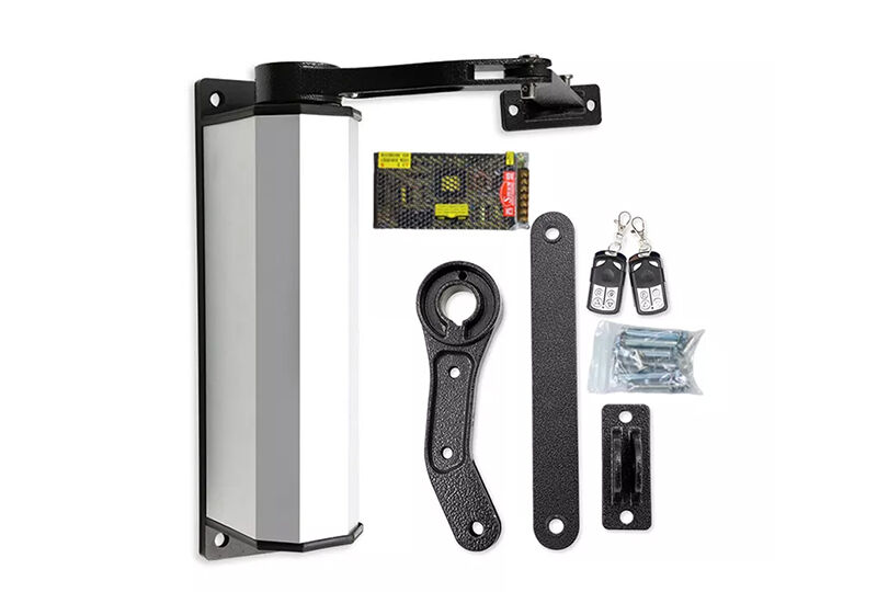
The mechanical installation begins with a correct identification of the door's opening direction: clockwise opening is designated as "left opening," while counterclockwise is "right opening." The main unit must be mounted vertically on the door post. The installation process involves securing the door opener body using the specified dimensions, then attaching the crank assembly to the spindle. Great care must be taken to align the keyway on the crank with the key on the spindle to ensure a secure and proper fit. Once the crank is locked in place with shims and screws, the L-type mounting seat is fixed to the door using the provided M8 hardware. A critical detail during this phase is to ensure that the L-type mounting seat, the crank and the main shaft of the door opener are all on the same horizontal plane. If they are not aligned, the crank will experience undue stress, leading to mechanical binding or obstruction.
三、Electrical Connections and Parameter Configuration
The electrical wiring process demands meticulous attention to safety and correctness. All connections must be made with the power supply disconnected, and it is only after all wiring is complete that the system should be energized. A critical warning is provided against reversing the positive and negative poles of the power supply, as this will result in immediate damage to the controller board. Specific recommendations are given for the electromagnetic lock, which should be a 12V DC unit with a power draw of less than 9W. The control terminal block accommodates several key connections: the 24V DC power supply, the 12V output for the electromagnetic lock, the fire linkage input, and the opening control signal from an access control system or push button. The manual provides clear distinctions between connecting a dry contact (switch quantity) and a wet contact (voltage output) from an access control device, with instructions on when a transfer module is required.
Following successful installation and wiring, the system requires configuration. When powered on for the first time, the door opener automatically enters a learning state to determine the closed position. Once this position is learned, the system enters standby mode. The heart of the configuration is the circuit board, which features a 3-bit LED digital tube display and three push buttons for navigating through a comprehensive menu of parameters. These parameters, identified by codes like P01 through P26, allow the installer to adjust virtually every aspect of the door's operation. This includes setting the opening and closing speeds, adjusting the buffer speeds and angles, determining the holding time and configuring current detection thresholds to optimize torque and safety. The manual also details a series of status displays, such as H01 to H09, which indicate the door's current operational phase and error warnings like E01 to E04, which are invaluable for diagnostics.
四、Debugging, Troubleshooting, and Final Notes
The debugging phase is essential for fine-tuning the system to its specific environment. This process involves confirming the learning of the closed position and adjusting the door's opening angle by modifying the P13 value. The speed of both opening and closing can be tailored using P10 and P01, respectively. A critical part of debugging is the adjustment of the backstepping current (P06), which protects the motor from overloading. If the door meets resistance and the digital tube displays the "H08" alarm, the current setting should be increased to prevent nuisance tripping. Similarly, if the door struggles to close completely, increasing the low-speed current (P19) or buffer speed (P02) can provide the necessary extra torque.
The final chapter of the manual provides a valuable guide to common faults and their remedies. This troubleshooting section covers scenarios ranging from the unit failing to power up, where checks for 24V at the power input terminals are recommended, to specific alarms like the "H08" overcurrent protection. For each potential fault, a structured approach to diagnosis and a list of corrective actions, such as adjusting parameters, checking mechanical obstructions, or replacing specific components, is provided. Finally, a comprehensive packing list assures the user that all necessary components, from the main unit and crank assembly to optional accessories like remote controllers and infrared sensors, are included for a complete installation.

 Hot News