Comprehensive Summary and Operational Guide for the PD Series Sectional and Tilting Door Opener
This document is an official installation and user manual for the PD Series (Models PD 800, PD 1000, PD 1200) garage door openers. It is a technical document intended primarily for qualified installers but also contains crucial safety, programming and troubleshooting information for end-users. The manual covers everything from initial mechanical installation and assembly to advanced electronic feature programming and diagnostics.
Critical Safety and Preliminary Warnings
The manual begins with a stern warning: installation must be carried out by a technically qualified or licensed person. Attempting installation without suitable qualifications risks severe personal injury, death or property damage. The manual emphasizes that the opener is designed to assist a well-balanced door, not to compensate for a poorly installed or damaged one. A garage door that is hard to move by hand must be fixed before installation.
Key safety instructions include:
1. Disconnecting the power supply during cleaning or maintenance.
2. Keeping remote controls away from children and never allowing them to play with door controls.
3. Exercising extreme caution when using the manual release, as a door with weak or broken springs may fall rapidly.
4. Monthly testing of the safety reversal system using a 50mm high object on the floor.
5. The Safety Obstruction System is designed to work on stationary objects only. Contact with a moving object could cause severe injury.
The manual also strongly recommends the addition of Photocell sensor as an extra safety layer, despite the opener having a built-in pressure-sensitive obstruction force system.
Mechanical Installation Overview (Key Mechanical Steps)
The installation instructions detail the physical mounting of the opener, which is critical for its safe and reliable operation.
1. Preparation: Ensure the garage door is well-balanced and moves easily by hand. Remove any existing locking devices from the door. A minimum gap of 30mm must be maintained between the bottom of the chain drive rail and the top of the garage door at its closest point.
2. Bracket Mounting: The wall bracket is mounted 2cm to 15cm above the closed door on the inside wall, centered. The door bracket is fixed to a structural part of the door as close to the top edge as possible.
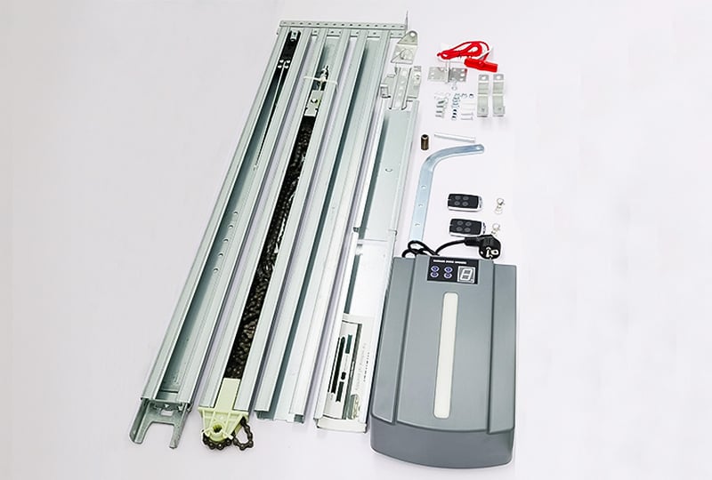
3. Track Assembly: The steel track (available in 2 or 3 parts) is assembled by sliding rail sections into connecting sleeves. The screw rod and inner chain are then pulled to the end rail position and a nut and spring are tightened to complete the track assembly.
4. Head and Track Positioning: The opener head is attached to the track, and the assembly is placed centrally on the garage floor. The front of the track is lifted and connected to the door bracket using a pivot pin and split pin. The opener head is then lifted, leveled and fixed to the ceiling using the supplied iron hanging brackets.
5. Arm Connection: The straight and bent arms are bolted together and then attached to the top edge of the door. Finally, the garage door is lifted until the trolley (shuttle) locks into the drive chain or belt, making the mechanical connection ready for programming.
Advanced Electronic Features and Programming
A significant portion of the manual (pages 10-21) is dedicated to setting up sophisticated electronic features using a control panel with a digital display and SET, UP, DOWN and CODE buttons.
Core Programming - Limits and Force:
1. Setting Open & Close Limits (Function 1): This is the fundamental setup. The user puts the unit into programming mode, then uses the UP and DOWN buttons to move the door to the desired fully open and fully closed positions, pressing SET to confirm each. After confirming the close position, the door automatically cycles open and closed to learn the travel limits and automatically adjust the force sensitivity. A critical caution states that after this cycle, the display will show a figure (0-9). "0" means the door is perfectly balanced; a smaller figure is better. The manual strongly recommends this figure be smaller than the "power force."
2. Obstruction Force Adjustment (Function 2): While this is set automatically during programming, it can be manually adjusted from a minimum force level of "1" to a maximum of "5." The factory default is "3."
Convenience and Customization Features
1. Travel Speed Setting (Function 3): Allows the user to set the door's travel speed to either 80% (display shows "8") or full speed, which is 160mm/s or 200mm/s (display shows "A").
2. Auto-Close Function (Function 4 & 5): This feature automatically closes the door after a set time. The delay time is adjustable in 15-second increments (N=0-9), with a maximum of 135 seconds. Setting the time to "0" disables the function. The manual strongly recommends using Safety Photo Beams with this feature. An additional condition setting (Function 5) defines if auto-close only works when the door is at the open limit ("1") or from any position ("2").
3. Partial Open/Height Setting (Function 8): Sets the door to only open partially (e.g., for ventilation or pet access). The display can be set from "1" to "9" to define the open position as a tenth of the whole travel or "0" to disable the function.
4. Transmitter Button Recognition (Function 9): When closed ("0"), any of the 4 buttons on a single remote will operate the door after one button is coded. When open ("1"), only the specific button that was coded will operate that door, allowing up to 4 different doors to be controlled by one remote.
5. LED Courtesy Light Delay (Function 6): The courtesy light turns on with each cycle and its off-delay time can be set from 1 to 9 minutes (factory default is 3 minutes).
Safety and Maintenance Features
1. Reversal Height Setting (Function 7): Defines how the door reacts when it hits an obstruction while closing. A setting of "0" makes the door rebound fully to the open position. Settings "1-9" make it rebound to a specific point (e.g., one-tenth to nine-tenths of the travel).
2. Reversal Height Ignorance Setting (Function b): A specialized feature for snowy climates. It allows the door to ignore an obstruction in the last 1cm to 9cm of its close travel, preventing it from reversing due to snow on the ground.
3. Photo Cell On/Off (Function d): This must be set to "1" (on) only if photocell sensor are physically installed and connected. If set to "0" (off) but photocell sensor are connected, or "1" with no beams, the door will not close correctly and the display will show an "r".
4. Maintenance Alarm (Function E): This programmable counter can be set to trigger after 1,000 to 5,000 operation cycles. When triggered, the LED light flashes 10 times quickly and a "t" appears on the display, indicating the door needs professional maintenance.
Troubleshooting and Specifications
The final sections provide a practical troubleshooting table for common issues (e.g., opener not working, display not bright, unexpected reversal, remote control problems) with corresponding causes and solutions. For example, if the opener stops after 10cm and a specific code shows, the manual points to a loose or damaged Hall sensor wire. If the display shows "t" constantly, it means the garage door system needs total maintenance.
The technical specifications table confirms the PD 800, 1000 and 1200 models provide 800N, 1000N and 1200N of pull force, suitable for door areas up to 10m², 15m² and 18m² respectively. All models use rolling code technology (433.92 MHz) for security, have an IP20 protection rating, and operate in temperatures from -40°C to +50°C.
In summary, this manual is a complete technical guide for a sophisticated, feature-rich garage door opener. It successfully balances the need for strict, safety-critical installation instructions with clear guidance on advanced programmable features, making it a valuable resource for both professional installers and technically inclined end-users.


 Hot News
 EN
EN