Beyond the Manual: Strategic Insights for Installing the 125 Series Automatic Sliding Door System
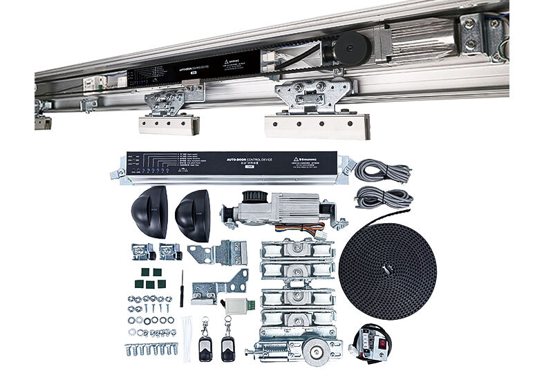
The 125 Series automatic sliding door system represents a sophisticated integration of microprocessor-controlled motion, DC brushless motor technology and modular mechanical design. While the installation manual provides essential step-by-step guidance, achieving long-term reliability, safety and performance optimization requires a deeper understanding of the system’s engineering logic, potential failure points and the rationale behind each procedural requirement. This analysis reinterprets the manual’s content through the lens of practical innovation, offering installers and facility managers actionable insights that go beyond routine checklist execution.
Rethinking Guide Rail Installation: Precision as a Structural Imperative
Motor and Controller Placement: Thermal Management and Cable Dressing
The motor installation procedure (inserting the bracket into upper and lower rail grooves) is mechanically straightforward, but the manual’s caution about misoperation leading to falling off is significant. An innovative approach is to pre-assemble the motor bracket with anti-vibration pads, even if not explicitly required, to dampen high-frequency oscillations that can transfer into the rail structure. The instruction to route the motor cable through the top and out the left side is not arbitrary—it prevents the cable from contacting moving belts or hangers. For the controller, positioning it midway between the motor and idle pulley minimizes signal path length for the terminal switch and reduces electromagnetic interference. In installations with backup batteries or electric locks, the controller should be positioned away from potential water ingress points, such as near entrance seals or unsealed wall penetrations.
Hanger Alignment and Door Leaf Dynamics: The 0.5mm Rule
Belt Installation and Tension Calibration: Dynamic vs. Static Tension
Safety Systems and Sensor Integration: Eliminating Blind Zones
The safety precautions section is emphatic about ensuring the detection range covers the full opening area without blind spots. For sensor installation at 2.2–3.0 meters height, the cone of detection must overlap across the entire door width. A practical innovation is to perform a “walk test” with a reflective object (e.g., a cardboard sheet) moved along the door’s path while observing the sensor’s indicator LED. Any position where the LED fails to light indicates a blind zone requiring sensor repositioning or the addition of auxiliary safety beams. The manual’s warning against mixing sensors from different manufacturers due to varying wiring voltages is often ignored, leading to controller damage. A safer approach is to standardize on one sensor model per installation and keep spare wiring harnesses pre-labeled.
Electrical Connections and Optional Accessories: Passive vs. Active Outputs
For code card readers, the requirement for passive output is frequently misunderstood. Passive outputs act as simple switches (dry contacts), while active outputs supply voltage. Connecting an active-output reader to the controller can inject voltage into signal lines, causing erratic behavior or permanent damage. If an active reader must be used, install an isolation relay. Similarly, for two-door interlocking, the sequence logic ensures one door cannot open while the other is in motion. This requires correct polarity on interlock signal lines. For electric locks, the specified working current (<200mA) and starting current (<800mA) must be respected; exceeding these can weld lock contacts or blow controller fuses. The backup battery recommendation—charging for 24 hours initially and checking every six months—is often neglected. A maintenance log with battery replacement dates (every 2–3 years) prevents unexpected failures during power outages.
Parameter Adjustment: Beyond Default Settings
The 10-level parameter adjustment menu (opening speed, slow opening distance, closing speed, slow closing distance, slow speeds, hold-open time and function selectors) offers extensive customization. However, the manual’s factory recommendation of setting buffer speeds to 5 and distances to 7 is only a starting point. For high-traffic environments, reducing hold-open time to 2–3 seconds improves energy efficiency. For healthcare facilities, slower opening speeds with longer buffer distances reduce perceived aggression and improve safety for patients with mobility aids. The p-1 (automatic closing) versus p-2 (signal closing) selection changes operational logic entirely: p-2 is useful for cleanrooms or security zones where doors should only close upon explicit command. The left/right direction setting (p-L / p-r) must be verified from inside the building; a common mistake is setting direction based on exterior viewpoint, causing reverse operation.
Troubleshooting as a Diagnostic System
The troubleshooting guide lists symptoms and solutions, but an innovative installer builds a diagnostic flow: (1) disconnect power and manually move the door to distinguish mechanical friction from electronic issues; (2) observe the controller display for flashing patterns during fault conditions; (3) temporarily remove optional accessories (sensors, safety beams, card readers) to isolate the base system. The symptom “door keeps opening/closing with no stop” often points to RF interference or a shared detection area—solved by changing anti-interference switches on sensors or physically separating detection cones. For collision issues, slow, incremental adjustments (clockwise or counterclockwise on the relevant potentiometers or digital settings) prevent overshoot. The note that the test button should only be pressed after unlocking an electric lock is critical; attempting to test while locked can bend linkages or damage the lock mechanism.
Long-Term Reliability: Environment and Usage Patterns
The operating temperature range (-20°C to 50°C) is broad, but battery life shortens dramatically outside 0–40°C. In cold climates, consider insulating the controller enclosure. In corrosive gas or high-humidity environments (e.g., indoor pools, chemical storage), the manual explicitly advises against installation because electronic traces and motor windings will corrode. For such locations, a pneumatic or hydraulic operator is more appropriate. Finally, the adhesive sticker warning—though seemingly minor—serves a real safety function: pedestrians approaching a clear glass sliding door may not perceive the moving leaf, and the sticker provides visual contrast. Placement at eye level (approximately 1500mm from floor) maximizes effectiveness.
By adopting these innovative, experience-based refinements to the manufacturer’s instructions, installers can reduce callbacks, extend system lifespan, and achieve a level of performance that standard compliance alone cannot guarantee. The 125 Series is a robust platform when treated not as a collection of parts but as an integrated electromechanical system requiring precision, foresight and adaptive maintenance.
 Hot News
2026-03-11
Copyright © 2026 Chisung Intelligence Technology (Shenzhen) Co., Limited All rights reserved. - Privacy policy