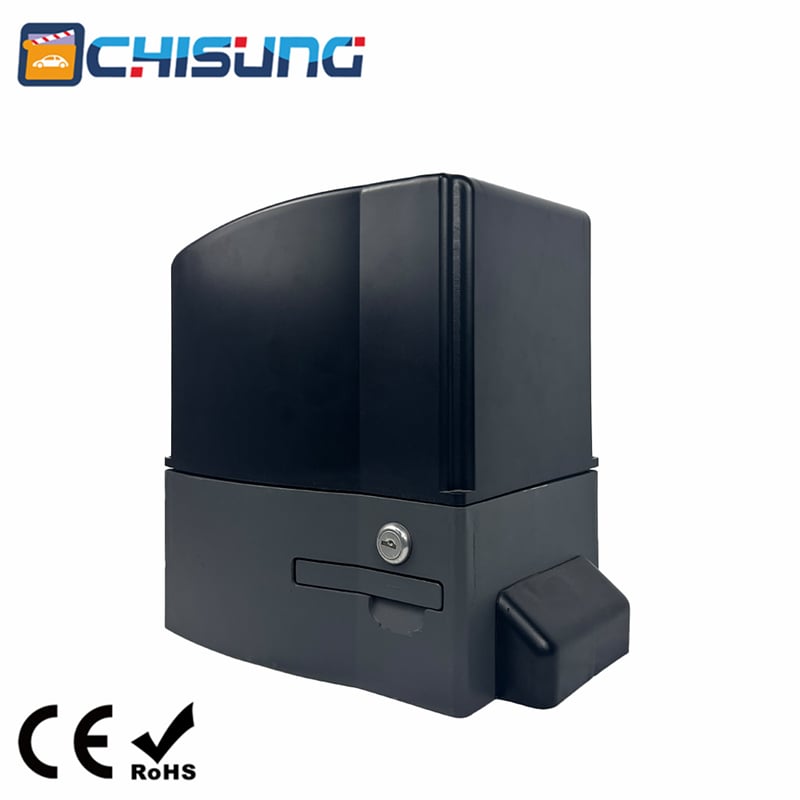
Technical Overview and Safety Protocols for the S11 Series Sliding Gate Opener
The S11 series sliding gate opener is a robust electromechanical device designed for automating sliding gates in residential, commercial or light industrial settings. The series includes different models—specifically the LW550, LW400, and LW370—each tailored to support gates of varying weights and sizes. The manual provides comprehensive instructions regarding technical specifications, mechanical installation, rack mounting, limit switch adjustment, troubleshooting and essential safety information. Understanding and adhering to these guidelines is critical to ensure safe, reliable and long-lasting operation of the gate system.
Main Technical Parameters and Model Specifications
The device is powered by either a 220V±10% or 110V±10% AC power supply, making it adaptable to regional electrical standards. The motor operates at a fixed rotational speed of 1400 revolutions per minute (rpm), which is reduced via an internal gearbox to an output rotational speed of 46.6 revolutions per minute. This reduction provides the necessary torque to move heavy gates at a consistent linear speed of 12 meters per minute. The environmental tolerance is extensive, with the unit capable of operating in temperatures ranging from -45°C to +55°C, ensuring functionality in extreme climates. The protecting class is IP44, meaning the device is protected against solid objects larger than 1 millimeter and against splashing water from any direction. Regarding gate weight capacity, the LW550 model can handle gates weighing up to 1500 kilograms, and when installed correctly, it can manage gate lengths up to 20 meters. The LW400 model supports gates up to 800 kilograms, while the LW370 model is rated for gates up to 500 kilograms. The system utilizes either a spring limit switch or a magnetic limit switch to control gate travel and endpoints.
Important Safety Information and Precautions
The manual emphasizes a series of critical safety measures that must be observed before, during and after installation. Incorrect installation or misuse of the product may cause serious harm to people. Therefore, before commencing any work on the system—whether installation, maintenance or repair—the electricity supply must be turned off completely. The gate itself must move smoothly along its track without any binding or excessive friction; any mechanical resistance can overload the operator and create a hazard. Users are strictly warned against making any alterations to the components of the device, as modifications can compromise safety mechanisms and structural integrity. The manual explicitly states that safety devices—such as photocells, safety edges or other external sensors—must be used to prevent any potential risk of crushing, shearing, or impact. The end user must refrain from attempting to repair or adjust the system personally; only professional personnel should perform such tasks. The installer is responsible for supplying the system user with complete information regarding the operation of the system in the event of an emergency, as well as providing the manual. The manual should be kept in a safe place for future reference.
Mechanical Installation and Operator Base Mounting
The sliding gate operator must be installed on the inside of the gate, as illustrated in Fig.1 of the manual. The mechanism operates by forcing a drive rack via a drive gear; the entire configuration relies on proper alignment between the gear on the operator and the rack attached to the gate. The installation process begins with preparing a concrete pad to serve as a stable foundation. Once the concrete has fully hardened, the operator base is mounted onto the pad. It is critical to verify that the base is properly leveled in all directions; an unlevel base will lead to misalignment between the drive gear and the rack, causing uneven wear, excessive noise and potential premature failure. Using the provided bolts and washers, the gate operator is secured to the base, after which the protective cover is inserted. The installer must then check the operator to ensure it is correctly lined up with the gate’s travel path.
Installation of the Drive Rack
The rack installation process is described in detail. Three nuts, supplied in the same package as the rack, are first fixed onto each rack element. The first piece of rack is laid onto the drive gear and the first nut is welded onto the gate. The gate is then moved manually to check whether the rack is resting correctly on the gear; if the engagement is proper, the second and third nuts are welded. Subsequently, another rack element is brought near the previous one, ensuring a continuous tooth profile. The gate is moved manually again and the three nuts for that new rack element are welded. This process is repeated until the entire length of the gate is covered with rack segments. After all rack segments have been installed, it is essential to verify that the rack meshes correctly with the gear. The manual specifies that the gap between the rack and the gear should be approximately 0.5 millimeters—a critical tolerance that ensures smooth engagement without excessive backlash or binding.
Adjustment of Limit Switches
To guarantee safe operation, limit switches are recommended at both ends of the gate. These devices prevent the gate from sliding out of the rails, which could cause derailment or structural damage. The rails themselves must be installed perfectly horizontally. The manual describes two types: the spring limit switch and the magnetic limit switch, both using blocks or magnets to control the gate’s open and closed positions. The adjustment procedure begins by releasing the gear using the release key, which disengages the motor from the drive train. The sliding gate is then pushed manually to pre-determine the desired open and closed positions. The limit block is fixed to the rack at those positions and the release bar is pushed up to lock the gear back into engagement with the rack. Finally, the gate is moved electrically and the position of the block is fine-tuned until the opening and closing stops meet the required positions accurately.
Troubleshooting Common Issues
The manual provides a structured troubleshooting section. If the motor cannot work at all, potential causes include no power supply, a blown fuse, capacitor decay, surpassing the load limit or activation of the thermal protection. Solutions involve checking the power supply, replacing the fuse or capacitor, clearing barriers on the track and restarting after 20 minutes of cooldown. If the gate can open but cannot close or vice versa, the issue likely lies with the limit switch position, a damaged limit switch or a magnetic steel that has dropped or been positioned incorrectly. Adjusting the position, replacing the switch or re-adjusting magnetic steel position are the remedies. Inaccurate positioning of the gate can result from excessive distance between limit switches, a damaged switch or incorrect magnetic steel position. If the clutch fails to operate, the operating handle may be broken or the clutch may be jammed; replacing the handle or rotating the output gear in both directions to free the jam are the solutions. If pressing the remote control button yields no motor response, the remote’s battery may have no signal and should be replaced. Finally, if the motor can be heard humming but cannot drive the gate, the compression spring of the clutch may be worn out or the clutch may be in a released state; replacing the spring or closing the clutch will resolve this.
Packing List and Final Notes
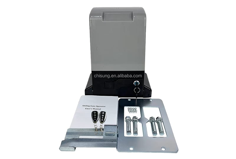
Upon receiving the gate operator, the user should perform an unpacking inspection to check for any damage. The standard packing includes one sliding gate operator, two transmitters, one release key and one user’s manual. For any problems, the user should contact the dealer. The manual concludes by directing users to separate manuals for detailed control board settings.


 Hot News
 EN
EN