Comprehensive Safety, Installation, and Operational Guide for the CSSGO-12 Automated Gate Opener
General Safety Warnings and User Responsibilities
The CSSGO-12 automated gate system is designed to provide professional-grade gate solutions. However, like any electromechanical system, it presents potential hazards if not installed, used and maintained correctly. The manufacturer emphasizes that user safety is paramount. Before operating or attempting any work on the system, all users and installers must read and fully understand the following safety instructions.
1. Keeping a Safe Distance: All adults, children and pets must remain outside the operational range of the automated system, particularly while the gate is in motion. The moving gate exerts significant force and can cause serious injury if it strikes a person or animal. Additionally, personal property, including vehicles, bicycles and garden equipment, should be stored clear of the gate’s path to prevent damage and ensure unobstructed operation.
2. Supervised Use by Vulnerable Individuals: This unit may be used by children over the age of 8 years, as well as individuals with reduced physical, sensory or mental capabilities or those lacking experience and necessary knowledge, but only under strict conditions. Such users must be properly supervised by a responsible adult or have received comprehensive training regarding the safe use of the equipment. Furthermore, they must fully understand the inherent risks involved, such as the risk of entrapment or impact. Under no circumstances should children be allowed to play with the gate or its controls. The remote controls and any other activation devices must be stored in a location inaccessible to children to prevent inadvertent or unsupervised operation.
Pre-Operational Inspection and Mechanical Integrity
Before each use or at regular intervals as determined by a professional installer, the mechanical parts of the gate itself—not just the opener—must be inspected. The gate is referred to in the manual as the "operated part." Components such as cables, springs, supports, hinges and rollers are subject to wear and fatigue over time. A breakage or significant wear of any of these parts can create a severe hazard, potentially causing the gate to fall, bind or move erratically. Therefore, a qualified, expert personnel (professional installer) must check the entire system at regular intervals according to the instructions provided by either the installer or the door manufacturer.
Maintenance, Cleaning, and Repair Protocols
1. Cleaning Procedures: When cleaning the exterior of the gate or the opener mechanism, it is mandatory to first cut off the mains power supply to the unit. This precaution prevents accidental activation during cleaning, which could lead to injury or damage to the system components. Do not use high-pressure water jets directly on the motor housing or any electrical connections, as moisture ingress can cause short circuits or corrosion.
2. Fault and Breakdown Response: Never use the automated system if it is known to be in need of repair. In the event of a breakdown, malfunction or unusual behavior—such as erratic movement, excessive noise or failure to respond to controls—the user must immediately cut off the mains power to the system. Under no circumstances should an untrained person attempt to repair the unit or perform any work to rectify the fault themselves. Doing so not only voids warranties but also introduces serious electrical and mechanical risks. Instead, contact qualified, expert personnel (a professional installer) to perform all necessary repairs or maintenance.
3. Scope of Work: If any part of the automated system requires direct work of any kind that is not explicitly described in this manual, the user must employ the services of qualified, expert personnel. This includes modifications, additions, replacement of non-consumable parts or any internal adjustment beyond the basic user-level settings.
4. Annual Professional Inspection: At least once per year, have the entire automated system, with special emphasis on all safety devices (such as photocells, safety edges, and torque limiters), checked by a professional installer. This inspection ensures that all safety mechanisms remain undamaged, correctly aligned, and fully functional. The operating environment can degrade sensors and mechanical parts over time, so annual verification is critical for continued safe operation.
User Limitations and Manufacturer’s Rights
Anything that is not explicitly provided for in this manual is not permitted. The proper, reliable and safe operation of the gate opener can only be guaranteed if all instructions given herein are strictly complied with. The manufacturer (the Firm) shall not be held answerable for any damage to property or injury to persons caused by failure to comply with the instructions, warnings and procedures featured in this manual. This includes damage resulting from unauthorized modifications, improper use, neglect of maintenance, or installation by unqualified persons.
While the Firm will not alter the product’s essential safety or functional features, it reserves the right, at any time, to make changes deemed opportune to improve the product from a technical, design or commercial point of view. Consequently, the Firm will not be required to update this publication to reflect such improvements, nor will it be obligated to retrofit existing products with new features.
Product Description and Technical Overview
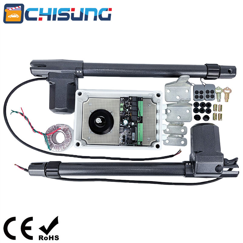
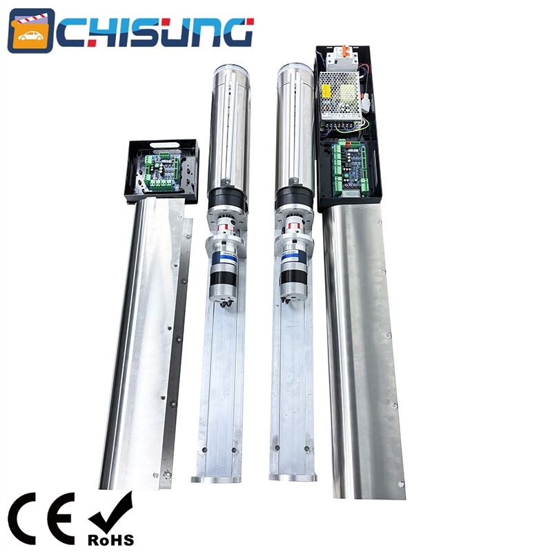
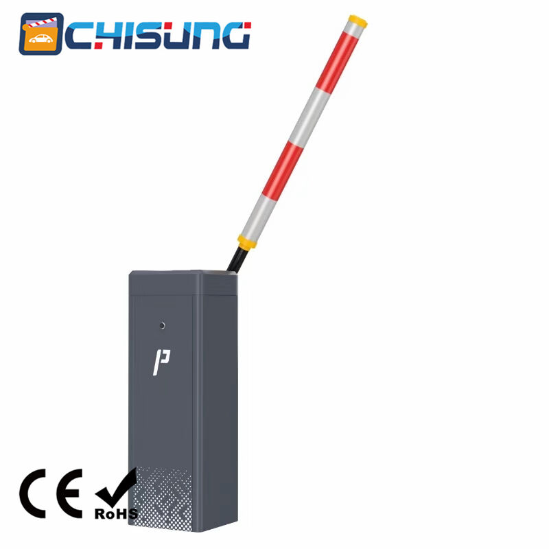
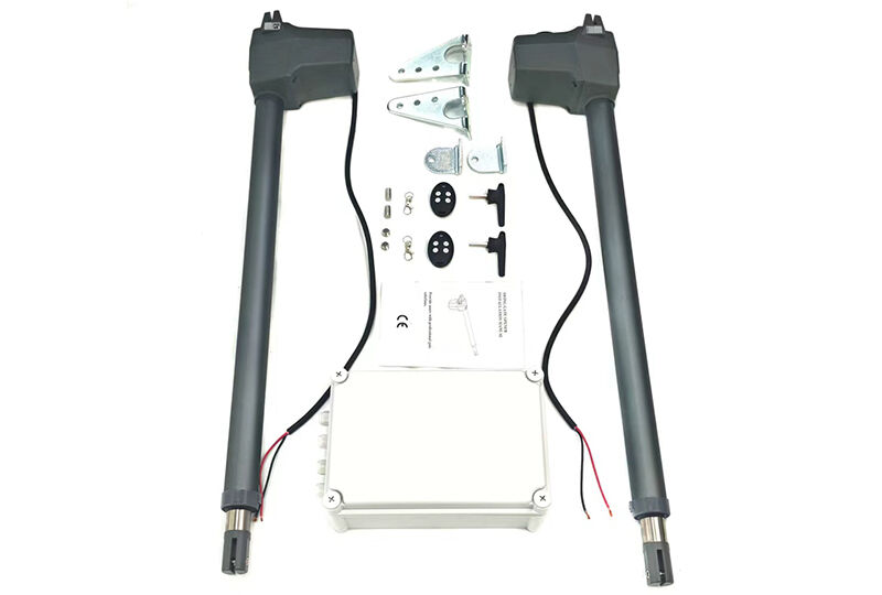
The CSSGO-12 automated gate opener is an electromechanical linear actuator designed for swinging gate leaves. The main components visible externally are: the electric motor, which provides the driving force; the power cable for mains connection; two mounting brackets (designated Bracket A and Bracket B) for attaching the opener to the gate leaf and the pillar; the piston rod, which extends and retracts to move the gate and the protection tube, which shields the internal screw mechanism from dust, moisture and impact.
1. Technical Specifications (Descriptive Format): The opener is available in multiple models to suit different gate sizes and weights. The power supply options include AC 230V (common in Europe and many other regions) or AC 120V (standard for North America). A dedicated DC 24V model is also available for low-voltage or battery-backed systems.
2. Motor power ratings vary: the 400 and 600 models draw 180W under normal operation, while the 400/600 model operates at 80W, likely due to a different gearing or duty cycle design. The maximum leaf length supported ranges from 2.5 meters for the 400 model up to 3.0 meters for the 600 and 400/600 models. Correspondingly, the maximum leaf weight supported is 300kg for the 400 model and 350kg for both the 600 and 400/600 models.
All models feature thermal protection that activates at 150°C to prevent motor burnout during overload or extended use. The operating temperature range is exceptionally broad, from -45°C to +70°C, making the opener suitable for extreme climates. The stroke length (the distance the piston rod travels) is either 400mm or 600mm depending on the model. Use frequency is rated at 25% for the 400 and 600 models, meaning they should have a rest period three times longer than their operating period. The 400/600 model is rated for continuous use, suitable for very high-traffic applications.
Installation Dimensions and Bracket Mounting
Proper installation begins with correct dimensional planning. The installer must measure the distance between the pillar (post) and the gate leaf at both the closed and open positions to ensure the opener has sufficient leverage and a full range of motion.
1. Mounting on Iron Pillars: If the pillar is made of iron, the recommended method is to weld the supplied mounting plate directly to the pillar. Alternatively, the installer may mark the positions of the plate’s holes, drill 8.5mm diameter holes at the marks, place M10 threads (using a tapping tool) and then fix the plate securely with M10 steel screws.
2. Mounting on Masonry Pillars: For pillars constructed of brick, concrete block or stone, the process requires masonry anchors. Mark the hole positions on the pillar, then drill holes with a diameter appropriate for the chosen expansion anchors (consult anchor manufacturer’s instructions, typically larger than 8.5mm for concrete). Clean the holes of dust, then insert and tighten the anchors securely.
Fixing the Motor and Manual Release Operation
Once the brackets are installed on both the pillar and the gate leaf, the motor unit is attached to these brackets using the provided pins and securing clips. The motor body should be level and free from twisting forces when the gate moves through its arc.
Manual Release Mechanism: This is a critical feature for operation during power outages or emergencies. The manual release uses a hexagonal (hex) key. For the left-side opener (when facing the gate from inside the property), turning the hexagonal releasing key clockwise will disengage the internal gearbox, allowing the gate to be moved by hand. Turning the key anti-clockwise re-engages the mechanism, locking the gate opener back into motor-driven mode. For the right-side opener, the action is the opposite: clockwise locks the unit and anti-clockwise releases it. This mirroring ensures that turning the key in the same direction (e.g., clockwise from the outside of the property) releases both gates on a dual-leaf system.
Post-Installation Verification
After completing the installation, it is mandatory to verify that the entire mechanism is properly adjusted. The technician must ensure that the proportional force system (which limits the motor torque to safe levels) is correctly configured for the actual weight and friction of the gate. Furthermore, the manual release function must be tested to confirm it operates smoothly and allows full manual movement of the gate without excessive effort. Only after these checks are successfully completed should the automated system be put into regular service.

 Hot News