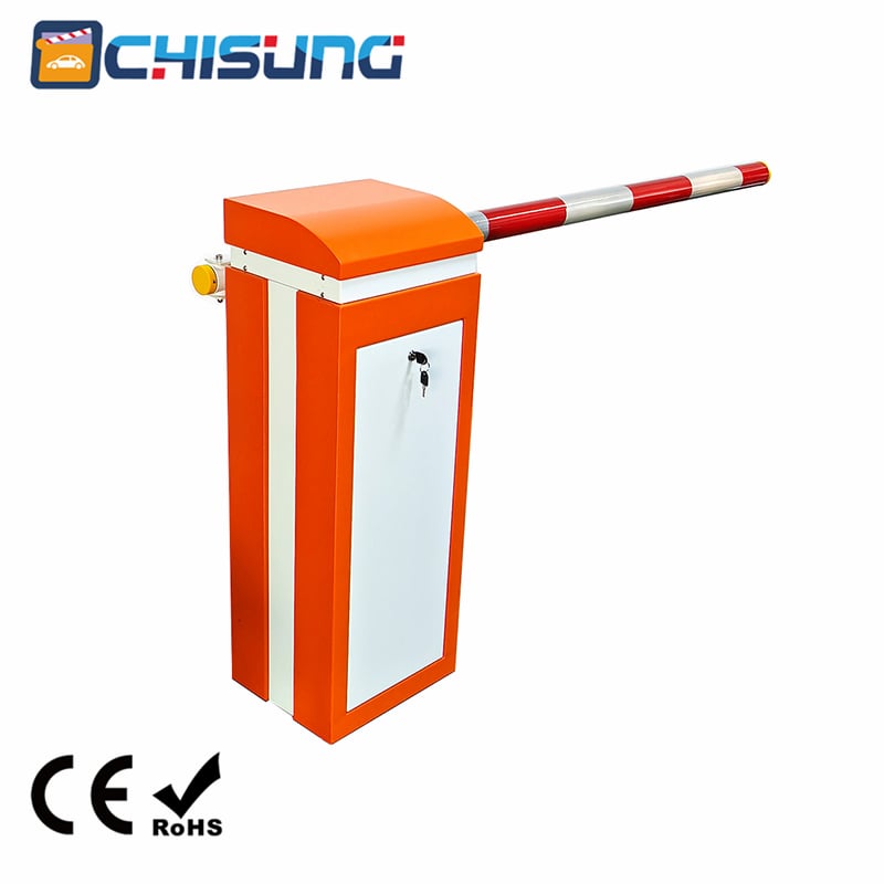
The CSKL04 Automatic Parking Barrier Gate Represents A State-Of-The-Art Solution For Modern Parking Facility Access Control. This Advanced Barrier System, Powered By A DC24V Planetary Motor, Combines High-Speed Operation With Exceptional Durability And Intelligent Control Features. Designed For 24/7 Operation In Demanding Environments, The CSKL04 Delivers Rapid Response Times While Maintaining Reliability And Ease Of Use.
The Product Architecture Comprises Five Primary Components: The Cabinet Cap, Cabinet Body, Transmission Mechanism, Control Unit And Boom Assembly. This Modular Design Facilitates Efficient Manufacturing, Maintenance And Customization To Meet Diverse Installation Requirements. The Barrier Gate Is Available In Left-Installed And Right-Installed Configurations, Accommodating Various Lane Layouts And Site Constraints. Three Boom Types Are Offered: Straight Boom, Folding Boom And Fence Boom Barrier, Providing Flexibility For Different Application Scenarios.
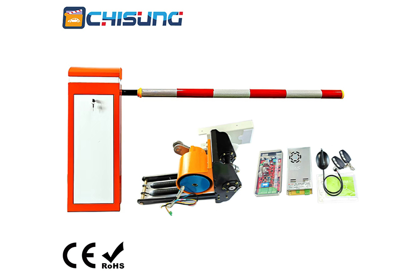
The CSKL04 Incorporates Advanced Engineering To Deliver Exceptional Performance Metrics. The Standard Configuration Features A 3-Meter Carbon Fiber Round Rod, Offering An Optimal Balance Between Strength, Weight And Durability. The Lifting Speed Achieves An Impressive Maximum Of 0.6 Seconds For The Carbon Fiber Boom Variant, While The Speed Range Is Adjustable From 0.6 To 6 Seconds, Allowing Customization Based On Specific Operational Requirements.
The Power System Utilizes A 240W Motor With 100% Load Period Rating, Ensuring Continuous Operation Without Overheating Concerns. The Power Supply Accepts 110/220V AC Or DC24V Input, With 50Hz/60Hz Frequency Compatibility, Making It Suitable For International Deployment. The Controller Operates On DC24V ±10% At 15A, Providing Robust Power Management For Consistent Performance.
Physical Dimensions Measure 350x300x980mm For The Chassis, With A Total Weight Of 69kg When Fully Assembled (20kg Machine Weight Plus 49kg Gate Weight, Excluding The Boom). The IP44 Protection Rating Ensures Resistance To Solid Objects Larger Than 1mm And Water Splashes From Any Direction, Suitable For Outdoor Installation. The Operating Temperature Range Spans -35℃ To 80℃ With 30% To 80% Non-Condensing Humidity Tolerance, Enabling Reliable Operation Across Diverse Climate Conditions. Remote Control Functionality Extends Up To 50 Meters In Open Environments And Chassis Color Customization Is Available To Match Site Aesthetics.
The CSKL04 Distinguishes Itself Through An Innovative No-Limit-Switch Design That Eliminates Traditional Mechanical Contact Sensors. This Clutchless Approach, Combined With Sensorless Technology, Enables Automatic Position Detection Upon Power-On, Dramatically Simplifying Installation And Reducing Maintenance Requirements. The System Automatically Identifies Both Vertical And Horizontal Positions Without Manual Intervention, Ensuring Consistent Operation Even After Power Interruptions.
The 240W Low-Voltage Frequency Conversion System, Paired With A High-Precision Two-Stage Planetary Transmission Gearbox, Achieves Comprehensive High-Precision Control Throughout The Entire Gate Cycle. This Advanced Transmission Architecture Ensures Exceptionally Smooth Opening And Closing Motions, Delivering Maximum Reliability At High Speeds. The System Supports 7×24 Hours Non-Stop Usage, Making It Ideal For High-Traffic Parking Facilities, Toll Plazas And Access Control Points Requiring Continuous Operation.
Over 95% Of Components Are Precision-Manufactured Using Industrial Robot Flexible Production Lines, Ensuring High Assembly Accuracy And Consistent Batch Quality. Metal Mechanical Components Undergo Comprehensive Anti-Corrosion And Anti-Oxidation Treatments, Substantially Extending Product Service Life. This Meticulous Manufacturing Approach Results In Exceptional Reliability And Reduced Lifecycle Costs. The Motor Demonstrates A Remarkable 2.5 Million Cycle Lifespan, While The Balanced Spring System Maintains 500,000 Cycle Durability.
During Power Outages, The Barrier Arm Can Be Manually Lifted Using The Supercapacitor Backup System, Allowing Vehicles To Exit Freely. Upon Power Restoration, The Barrier Automatically Returns To Its Normal Operating Position Without Requiring Manual Reset Or Recalibration. This Feature Ensures Continuous Access Control Even During Electrical Interruptions, Enhancing Operational Reliability.
The Auto-Reversing On Obstruction Function Detects Obstacles During Operation And Automatically Reverses Direction To Prevent Damage To Vehicles, Equipment Or Personnel. The Resistance Rebound Sensitivity Is Adjustable From 1 To 40 Units (With 0.05-Second Increments), With A Default Value Of 10, Allowing Fine-Tuning Based On Specific Environmental Conditions And Sensitivity Requirements.
The CSKL04 Offers Extensive Connectivity Options For Seamless Integration With Parking Management Systems And External Devices. The Rich Functional Interface Includes RS485 Communication, Loop Detector Connectivity, Radar Integration, Infrared Anti-Smash Sensors And Multiple Secondary Function Development Capabilities. The System Supports Activation Via Swipe Card, Push Button Or Remote Control Through Simple Dry Contact Signals, Enabling Comprehensive Automatic Management System Control.
The Controller Features A DC12V Power Output Delivering 1A Current, Suitable For Powering External Radar Units Or Small Light Strips. Relay Output Interfaces Provide Flexible Configuration Options, With Six Distinct Output Modes: Boom Lifting Alarm, Loop Detector Signal, Traffic Light Control (Two Modes), Pulse Signaling And Limit Signal Output. This Versatility Allows The Barrier To Function As A Central Component Within Larger Access Control Ecosystems.
Proper Installation Begins With Cement Island Construction, Requiring Dimensions Of 500mm (Length) × 500mm (Width) With A Depth Of 150-200mm. The Concrete Should Achieve C15 Rating Or Higher. The Distance Between The Barrier Cement Island Center And Roadside Must Exceed 300mm, Ensuring The Boom Can Open 90° On The Vertical Plane. Two 1-Inch PVC Conduits Must Be Embedded For Power And Control Signal Cabling.
The Cabinet Installation Procedure Involves Unpacking, Positioning The Unit On The Prepared Cement Island And Securing It With M12 Expansion Bolts. A 3mm Rubber Layer Is Recommended Under The Cabinet To Dampen Operational Vibration. The Installation Must Ensure Proper Alignment So That Booms Of Barriers In The Same Lane Form A Straight Line For Aesthetic Consistency.
Straight Boom Installation Requires Fixing The Boom Holder Press Board Using Two M12×70mm Hexagon Screws, Then Vertically Positioning The Boom On Its Holder. Flat Washers, Spring Washers And M12 Nuts Complete The Assembly. The Carbon Fiber Boom Option Weighs 49kg And Requires Proper Handling During Installation.
The Spring Balancing Mechanism, Factory-Adjusted For Specific Boom Types And Lengths, Requires Periodic Maintenance. Spring Force Adjustment Involves Manually Operating The Motor Hand Wheel With Power Off. If The Hand Wheel Cannot Turn Smoothly When Moving The Boom Toward The Closing Direction, The Spring Requires Tightening. Conversely, Difficulty During Opening Direction Movement Indicates Excessive Spring Force Requiring Loosening. Proper Spring Balance Results In Smooth Hand Wheel Operation Throughout The Full Range Of Motion. Boom Shaking During Opening Indicates Excessive Spring Force, While Shaking During Closing Suggests Insufficient Spring Tension.
The Intuitive Control Panel Features A Digital Tube Display, Function Buttons And Comprehensive Interface Connectivity. The Digital Tube Provides Real-Time Status Information Including IDLE (Motor Not Connected), STOP (Down Limit Position), CLOS (Closing), OPEN (Opening), HOLD (Up Limit Position) And LOCK (Brake Engaged). The Display Operates In Low-Power Mode After 60 Seconds Of Inactivity, Dimming To Reduce Consumption And Completely Turning Off After 30 Minutes To Minimize Energy Usage.
The Controller Supports Dual Menu Levels: Regular Menu And Advanced Menu. Accessing The Regular Menu Requires A 3-Second Press Of The Designated Button, Displaying "F-XX" Options. The Advanced Menu, Accessible Via Simultaneous Long Press Of Specified Buttons, Displays "H-XX" Options And Is Reserved For Professional Technicians.
Regular Menu Parameters Include:
The Advanced Menu Provides Sophisticated Configuration Options:
The Remote Control Learning Process Follows A Specific Sequence: Open → Close → Stop, With Each Button Held For One Second. Successful Learning Of All Three Buttons Results In A Long Buzzer Beep And The LED Displaying An Incremented Learned Count. The System Supports Learning Multiple Remote Controls Sequentially, With The Number Of Learned Remotes Displayed In The F-14 Menu. Learned Remotes Provide Operational Feedback Through Buzzer Confirmation On Button Press.
The Controller Displays Specific Error Codes For Rapid Problem Identification:
(1) Display E-03/E-04: Address By Increasing F-00/F-01 Speeds, Checking For Foreign Body Obstructions In The Mechanism, Or Adjusting Spring Tension Accordingly.
(2) Display IDLE: Verify Motor Wiring Connections And Check Motor Sensor Functionality; Replace Motor If Sensor Failure Is Confirmed.
(3) Controller Reset During Operation: Measure Phase Line Resistance Between Wires (White, Yellow, Red) Using A Multimeter To Verify Consistency; Replace Controller If Internal Failure Is Detected.
(4) Automatic Rebound During Closing: Increase F-15 Rebound Sensitivity Setting; Check Loop Detector Or Radar For False Signal Indications.
(5) Excessive Boom Shaking: At Up Limit Position, Reduce F-06 Speed Or Decrease Both F-06 And F-02 Deceleration Angles. At Down Limit, Reduce F-07 Speed And Increase F-03 Deceleration Angle.
(6) Remote Control Issues: For Short Transmission Distances, Replace Batteries Or Relocate Away From Interference Sources; For Learning Failures, Verify Remote Compatibility And Follow Correct Learning Sequence After Clearing Existing Codes.
(7) Improper Limit Positioning: Adjust F-08 For Vertical Position Or F-09 For Horizontal Position Parameters.
Proper Maintenance Ensures Optimal Performance And Extended Service Life. Monthly Inspections Should Verify All Joints Remain Securely Fastened. After 300,000 Operating Cycles, Spring Balance Requires Verification And Readjustment. Springs Should Be Replaced At 500,000 Cycles Or 12 Months Of Operation, Whichever Occurs First, To Prevent Fatigue-Related Failures.
Semi-Annual Inspections Should Examine Wear-Prone Components And Replace As Needed. Cabinet Cleanliness Must Be Maintained To Prevent Debris Accumulation Affecting Mechanism Operation. Remote Control Performance Should Be Periodically Verified, Noting That Transmission Distance May Decrease Due To Environmental Factors, Battery Depletion Or Signal Obstruction.
The CSKL04 Demonstrates Robust Performance Across Extreme Conditions, From -35℃ To 80℃ Operating Temperatures. Humidity Tolerance Of 30% To 80% Non-Condensing Ensures Reliable Operation In Both Arid And Humid Climates. The IP44 Protection Rating Provides Adequate Defense Against Environmental Exposure For Outdoor Installations.
The Product Includes A Comprehensive One-Year Warranty Covering Component Parts (Excluding Booms And Remote Controls). Beyond The Warranty Period, Lifetime Service Remains Available At Reasonable Charges. Technical Support Is Provided For Troubleshooting And Configuration Assistance. Exclusions From Free Service Include Damage From Improper Installation, Unstable Power Supply, Unauthorized Modifications, Natural Disasters Or Expired Warranty Coverage.
The CSKL04 Automatic Parking Barrier Gate Delivers Exceptional Value For Parking Facility Operators Requiring Rapid Throughput, Reliable Operation And Flexible Integration Capabilities. The 0.6-Second Opening Speed Significantly Reduces Vehicle Waiting Times, Improving Traffic Flow And User Satisfaction. The Robust Construction And High-Frequency Operational Capability Make It Suitable For High-Volume Applications Including Shopping Centers, Office Buildings, Residential Communities, Airports And Toll Collection Facilities.
The System's Intelligent Features, Including Auto-Recovery, Obstruction Detection And Motorcade Mode, Address Real-World Operational Challenges While Reducing The Need For Manual Intervention. The Comprehensive Connectivity Options Ensure Compatibility With Existing And Future Access Control Systems, Protecting Technology Investments. The Availability Of Multiple Boom Types, Custom Colors And Left/Right Installation Options Provides The Flexibility Needed For Diverse Site Requirements.
The CSKL04 Automatic Parking Barrier Gate Represents A Sophisticated Integration Of Mechanical Engineering, Power Electronics And Intelligent Control Technology. Its Combination Of High-Speed Operation, Durability And Advanced Features Positions It As A Premier Solution For Parking Access Control Applications. The Comprehensive Specification, Detailed Installation Guidance, And Robust Maintenance Framework Ensure Successful Deployment And Sustained Operational Excellence.
 Hot News
2026-03-11
Copyright © 2026 Chisung Intelligence Technology (Shenzhen) Co., Limited All rights reserved. - Privacy policy
 EN
EN