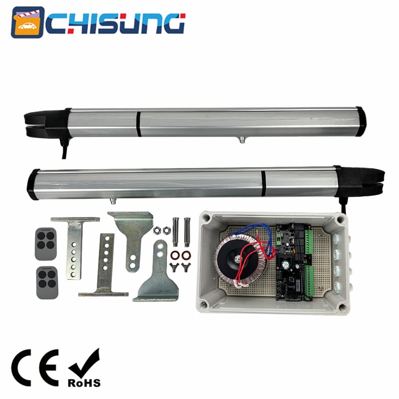
The CSPY-S12 is a professional-grade electromechanical gate operator designed for sliding gates in residential, commercial, and industrial settings. Its primary purpose is to automate the opening and closing of heavy gates, providing convenience, security, and controlled access. The system is engineered for reliability across extreme climates and heavy-duty cycles. However, the manufacturer explicitly states that this product must be used solely for the purpose for which it was installed. Any application beyond its specified design—such as lifting, swinging, or operating gates exceeding the weight or torque limits—constitutes improper use and voids all liability from the manufacturer. The manual emphasizes that the operator is not a toy and must be treated as a powerful piece of machinery capable of causing severe injury or property damage if mishandled.
Safety is the paramount concern throughout the manual. The document begins with a bolded "WARNINGS" section that establishes legal and practical responsibilities for both installers and end-users.
For Installers (Professional Personnel Only):
1.The installation must be carried out exclusively by qualified, expert personnel (referred to as "professional installers"). This is not a DIY product. Incorrect installation can lead to immediate failure, fire hazards, or catastrophic gate movement.
2.Before installation, the installer must verify the structural integrity of the existing gate (cables, springs, supports, and tracks). The manual warns that wear or breakage of these mechanical parts creates a hazard that the operator cannot compensate for.
For End-Users (Operational Safety):
1.Keep a safe distance: All adults, children, and pets must remain outside the gate's path during operation. The automated system moves with significant force (up to 2 TONs of gate weight) and cannot sense obstructions without additional safety devices (not covered in this basic manual).
2.Child safety: The unit can only be used by children over 8 years old or by persons with reduced physical, sensory, or mental capabilities if and only if they are under close supervision or have received specific training about the risks. Children must never play with the unit or its remote controls. Remote controls should be stored out of reach to prevent unintended activation.
3.Emergency response: If the system breaks down, malfunctions, or requires repair, the user must immediately cut off mains power. Under no circumstances should the user attempt internal repairs or adjustments. Only qualified personnel are authorized to service the system.
4.Periodic maintenance: At least once a year, a professional installer must inspect the entire automated system, paying special attention to all safety devices (limit switches, release mechanisms, and motor integrity). This annual check is mandatory to ensure undamaged and proper operation.
The CSPY-S12 series is available in seven distinct models, differentiated primarily by their output torque and maximum gate weight capacity. The common electrical supply is AC230/120V (with one variant supporting 380V AC). All models share a motor speed of 1400 RPM and a standard gate travel speed of 12 meters per minute, ensuring consistent opening/closing times regardless of gate size.
The torque ratings scale with the model: starting from 7 Nm for lightweight gates (300 kg) up to 45 Nm for the heaviest models supporting 2 TONs (2000 kg) . This linear progression allows installers to match the operator precisely to the gate's mass, avoiding under-powering (which causes motor burnout) or over-powering (which may damage lightweight gate structures).
Environmental resilience is a key feature: all models operate within a temperature range of -45°C to +65°C, making them suitable for arctic cold or desert heat. The noise level is consistently rated at ≤56 dB, which is quieter than a normal conversation, ensuring minimal disturbance. The protection class is predominantly IP44 (protected against solid objects >1mm and water splashes from all directions), except for the 1.5 TON 380V model which is rated IP41 (protection against falling water droplets). All units carry CE certification, confirming compliance with European safety standards. The manual explicitly notes that the manufacturer reserves the right to improve technical, design, or commercial aspects without updating this publication, so users should check for the latest revisions.
The physical installation begins with the steel basement—a critical load-bearing foundation. The manual stresses that the gate operator must be secured onto threaded bolts embedded in the basement. This is not a surface-mounted solution; it requires a prepared concrete plinth.
Critical Rule: The aluminum base of the gate operator must NEVER be in direct contact with concrete. Concrete is alkaline and can cause galvanic corrosion or chemical degradation of the aluminum housing over time. Therefore, the operator is mounted on steel studs or brackets that elevate it slightly above the concrete surface. The installer must ensure that the weight of the gate is not borne by the cog wheel (the output pinion). Instead, the gate's weight must be supported entirely by its own rollers or tracks. If the cog wheel supports vertical gate weight, it will cause premature wear, misalignment, and eventual mechanical failure. Figure 1 (referenced but not fully reproduced) illustrates the correct bolt pattern and basement dimensions.
The gear rack is the toothed bar that translates the motor's rotational torque into linear gate motion. The manual provides a highly practical, step-by-step method for fitting it:
1.Initial placement: Place the gear rack loosely on top of the gate operator's cog wheel.
2.Disengage the operator: Use the manual release mechanism to disengage the gearbox so the gate can be pushed freely by hand.
3.Progressive screwing: While pushing the gate along its track, allow the gear rack to ride over the cog wheel. As you push, screw the rack bit by bit firmly into position on the gate frame. This dynamic method ensures that the rack naturally aligns with the cog wheel's teeth, achieving optimal meshing without binding or backlash.
4.Marking fix points: The installer must mark each fixing point before final tightening to ensure the rack is straight and parallel to the gate rail.
5.Critical clearance: The manual mandates a gap of no less than 0.2 mm between the cog wheel and the gear rack bar. This gap prevents friction and thermal expansion binding, while still maintaining positive engagement. Too wide a gap causes skipping (stripping teeth); too narrow causes excessive wear and motor overcurrent.
In the event of a power outage or system failure, the operator is equipped with a lockable manual release mechanism (Figure 3). This mechanism includes a clutch that disengages the connection between the cog wheel and the internal gearbox.
Operation:
1.To release the gate (manual mode): Turn the release knob clockwise to the end. This mechanically separates the motor from the drive train, allowing the gate to be pushed open or closed by hand. This is essential during power cuts or for initial installation.
2.To re-engage (automatic mode): Turn the knob anti-clockwise to the end. This reconnects the gearbox, enabling remote control operation via transmitters.
Emergency override for broken limit switches:
The manual includes a critical troubleshooting note: if the limited switch is broken and the gate becomes blocked at the end of its travel (fully open or closed), turning the knob may not release the gate because the mechanical jam is at the limit. In such cases, the user or installer must unlock the four screws that fix the gate operator to the steel basement. This physically lifts or slides the entire operator off the rack, completely freeing the gate. This is a last-resort measure and must be performed with the mains power disconnected to prevent accidental restart.
Limit switches are essential for defining the gate's fully open and fully closed positions. The system supports two types: spring-loaded mechanical limit switches and magnetic limit switches.
For mechanical switches: Localizers (trip cams) and their brackets are mounted onto the gear rack at the approximate final travel positions. The spring of the gate operator's limit switch must just contact the incline of these localizers. As the gate moves, the spring is depressed, triggering the switch to cut power to the motor.
For magnetic switches (Figure 4): The manual specifies that the magnet must be positioned on the rack with the magnet pointing towards the motor. The magnetic contact sensor must be located in the middle of the motor housing for accurate detection. This non-contact method is more durable than mechanical switches. Both switch types use the same cable color coding for connection (detailed in Section 8).
Proper wiring is crucial for safe and reliable operation. The manual provides a clear color-coded system:
Motor cables:
1.Blue: Common (neutral)
2.Black and Brown: Open and Close (power phases for motor direction)
Mechanical limit switch cables:
1.Blue: Common
2.Black and White: Open and Close (normally closed contacts)
Magnetic limit switch cables:
1.Red: +12V DC power supply
2.Black: Ground (GND)
3.Green and White: Open and Close signals
The manual explicitly references a separate "Circuit board setting" manual. This indicates that while the power and limit wiring is straightforward, the programmable logic controller (PLC) or control board requires independent configuration for parameters such as motor run time, auto-close delay, and obstacle sensitivity. The installer must refer to that specific document to complete the setup. All connections must be made with mains power off, and cable glands must be used to maintain the IP44 protection rating.
The anufacturer's liability is strictly limited by compliance with this manual. The Firm disclaims all responsibility for damage caused by failure to comply with the instructions. The manual reiterates that anything not explicitly provided for is prohibited.
Mandatory annual service: A certified professional must check:
1.Mechanical wear on the cog wheel and gear rack.
2.Limit switch actuation accuracy.
3.Insulation resistance of motor windings.
4.Tightness of all foundation bolts.
5.Functionality of the manual release.
The user must never attempt to clean the exterior while the unit is connected to mains power—the power must be cut first. If any abnormal noise, vibration, or delay occurs, the system must be taken out of service immediately and a professional called. The manual concludes with a reminder that the Firm reserves the right to make product improvements without updating this publication, reinforcing that the user should always consult the installer for the latest application notes.
This summary serves as a complete reference for understanding, installing, and safely operating the CSPY-S12 gate operator. All instructions must be followed strictly to ensure warranty coverage and personnel safety.
 Hot News
2026-03-11
Copyright © 2026 Chisung Intelligence Technology (Shenzhen) Co., Limited All rights reserved. - Privacy policy
 EN
EN