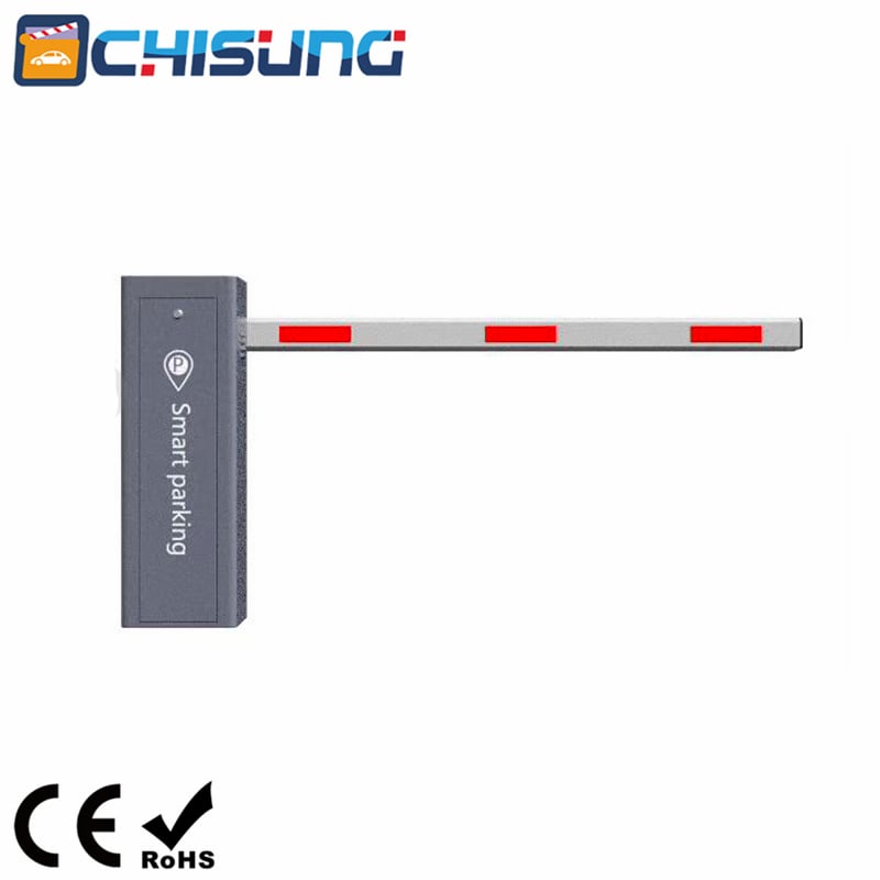
Technical Overview of the CSEDZ310 Barrier Gate System with V-Series Servo Controller
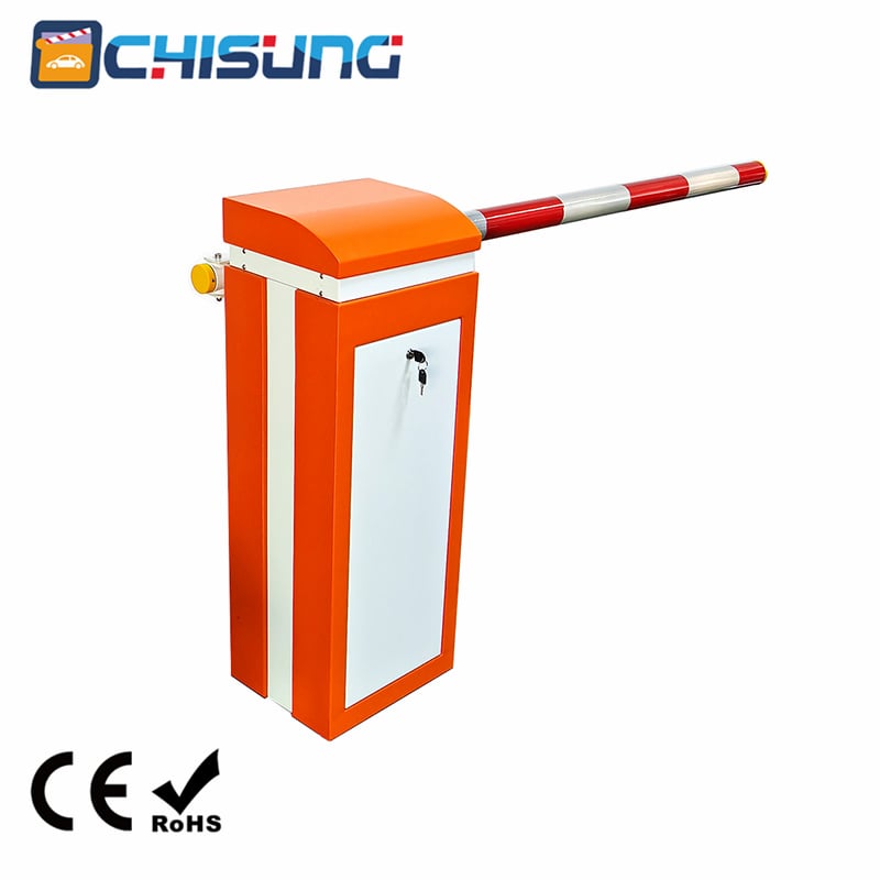
The CSEDZ310 barrier gate represents a modern approach to access control, integrating robust mechanical design with a sophisticated, digitally controlled servo system. This combination ensures reliable operation, precise control and enhanced safety for various vehicle access points, from commercial parking lots to industrial facilities. The system's architecture is built around a high-performance DC brushless motor, governed by an intelligent mainboard that offers extensive configurability.
I.Mechanical Design and Core Specifications
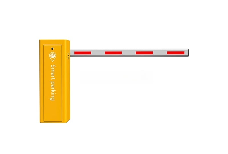
At its core, the CSEDZ310 barrier gate is engineered for durability and straightforward maintenance. The gate's foundation is a 1.5mm cold-rolled steel plate casing, which provides a sturdy housing for the internal components. The entire mechanism is designed with serviceability in mind; internal wiring is standardized to simplify troubleshooting and repairs and each unit is equipped with a dedicated power supply and an emergency power-off switch for safety compliance.
The gate lever is secured using a threaded tightening mechanism, ensuring it remains free from tilting or shaking during operation. This stability is crucial for the longevity of the mechanical components and the accuracy of the gate's position. The system supports a variety of pole types to suit different site requirements, including straight rods up to 6 meters, fence rails up to 4.5 meters and specialized options like telescopic rods and articulated booms. The pole itself is constructed from 6063-T5 standard aluminum, chosen for its excellent strength-to-weight ratio and corrosion resistance. The motor is a 150W DC brushless unit, featuring a precise steel gear structure. This setup is rated for an impressive mean time between failures (MTBF) of over 3 million cycles, underscoring its reliability in high-traffic environments. Furthermore, the system is designed to operate across a wide temperature range from -40°C to 80°C, making it suitable for deployment in diverse climates.
II.The V-Series Servo Controller: Intelligence and Connectivity
The intelligence of the CSEDZ310 barrier gate lies in its V-series servo controller mainboard. This unit serves as the central nervous system, managing motor control, sensor inputs and user commands. It is designed to interface with a standard 24V/10A power supply and a 24V DC brushless motor, which is the core of the system's actuation. The controller's versatility is evident in its extensive array of interfaces, which allow for seamless integration with external safety and triggering devices. These include connections for infrared beams, ground loops/radar, stop line control switches and a TTL nodular interface for more complex system integrations.
A key recommendation from the documentation is the use of BVR (flexible copper core) wires for all external signal connections, as opposed to network cables. This specification is a critical detail for ensuring signal integrity and reducing the risk of faults caused by line failures, highlighting a focus on long-term operational stability.
III.Advanced Commissioning and Adjustment Procedures
The commissioning process for the CSEDZ310 barrier gate is a multi-step procedure that ensures the gate operates smoothly and safely. Unlike simple on/off systems, this controller allows for granular adjustments to match the physical characteristics of the gate lever and spring.
The process begins with a physical balance check, where the gate lever is stopped at a 45-degree angle. The technician observes the lever's behavior to determine if the spring tension is correct; a slow drop indicates insufficient tension, while a slow rise suggests the tension is slightly high. Achieving a balanced mechanical state is the prerequisite for electronic fine-tuning.
Following this, the controller performs a self-learning or "self-check" limit switch process. This involves the mainboard automatically detecting the closing and opening limits of the gate. The user initiates this by holding a button on the mainboard, which then moves the gate to its mechanical limits and records these positions. This automated calibration is crucial for the motor's position awareness.
The system offers two distinct methods for adjusting the final horizontal (closed) and vertical (open) positions. The first is a direct, interactive method where a technician uses key combinations on the mainboard to jog the gate lever up and down until it is perfectly level or vertical. The mainboard then automatically saves these manually adjusted positions, effectively "teaching" the controller where the ideal endpoints are.
The second method is more data-driven, utilizing the controller's parameter menu. Here, the user can adjust specific parameters, such as L-6 for horizontal adjustment and L-9 for vertical adjustment, to incrementally change the stop position. For instance, if the gate lever closes to a point above the horizontal level, the L-6 parameter is decreased to correct it. This dual-mode approach to adjustment—direct teaching versus parameter tuning—provides flexibility for different maintenance scenarios and levels of expertise.
IV.Comprehensive Parameter Menu for Customization
The V-series controller features a deep parameter menu that allows for precise tuning of almost every operational aspect of the gate. The menu system is navigated using the mainboard's keys, offering a structured way to access and modify settings.
Key adjustable parameters include:
1. Speed Control: The opening and closing speeds can be independently adjusted via L-1 and L-2, allowing for customized traffic flow management. Higher values correspond to faster speeds.
2. Position and Stroke: Beyond the endpoint adjustments (L-6 and L-9), the controller also manages the deceleration stroke for both opening and closing (L-L and L-b). This feature allows for smoother operation by defining where the gate begins to slow down as it approaches its endpoints, preventing harsh stops and reducing mechanical stress.
3. Safety and Sensitivity: The L-4 parameter governs anti-crash sensitivity, determining how easily the gate detects an obstacle and reverses. A value set too low might cause the gate to auto-reverse without a real obstruction, while a value set too high might compromise safety. The anti-smashing force (L-c) is also configurable; setting this above a value of 100 effectively disables the rebound function, which is a critical consideration for specific operational contexts.
4. Operational Modes: The system includes a fleet mode (L-8 parameter set to 4), which is particularly useful for managing a stream of vehicles. In this mode, the gate remains open after the initial vehicle passes until a separate stop command is given, preventing the gate from closing on following cars. An aging test mode (L-7) is also available for automated testing cycles, demonstrating the controller's utility in quality assurance and maintenance.
V.Safety, Diagnostics and Remote Management
Safety is a paramount feature, integrated through multiple layers. The system supports connections for external safety devices like infrared beams and radar sensors. The documentation explicitly advises that remote control operation must only be used in conjunction with these sensors. Without them, the risk of vehicle impact due to improper timing or manual error increases significantly.
The controller is equipped with a comprehensive diagnostic system that displays error codes directly on the mainboard. For example, E-1 indicates an overcurrent condition, often pointing to a spring and pole mismatch. Error codes like E-2 help identify motor wiring faults, while E-3 and E-4 signal unauthorized rod lifting or pressing, which could be due to external force or incorrect spring tension. Codes like E-6 for "not in place" directly link to the spring and lever balance and E-9, E-L, and E-b help quickly identify if external sensors or stop ports are stuck in a signaling state. This diagnostic capability significantly reduces troubleshooting time, allowing technicians to pinpoint and resolve issues efficiently.
Remote control functionality adds to the system's convenience. The remote control pairing process is straightforward, executed through the mainboard menu. Users can also clear all paired remotes via the menu, a useful feature for security management. Finally, the system includes a simple method for restoring all parameters to factory defaults, which serves as a master reset to resolve configuration issues or start a fresh setup. The documentation emphasizes that after a factory reset, a full system restart is necessary for the new settings to take effect.
In conclusion, the CSEDZ310 barrier gate system, powered by its V-series controller, is a sophisticated piece of access control equipment. It blends robust mechanical engineering with an intelligent, feature-rich electronic control system. Its strength lies in its extensive adjustability—from speed and stroke to safety sensitivity and operational modes—ensuring it can be precisely tailored to the demands of any site while maintaining high standards of safety and reliability.


 Hot News
 EN
EN