A Comprehensive Guide to Install and Operate a DC24V Swing Gate Opener
Automatic gate systems offer unparalleled convenience, security and property value enhancement. However, the installation and maintenance of such systems are complex tasks that demand careful planning, technical knowledge and a strict adherence to safety protocols. This article provides a comprehensive overview of a typical DC24V swing gate opener system, drawing upon the critical information found in its official installation manual. It is intended to serve as a detailed guide for qualified installation personnel and an informative resource for property owners looking to understand the process.
The Primacy of Safety
Before any physical work begins, the manual for any gate automation system will emphasize safety and this model is no exception. The installation of an automated gate is not merely a mechanical task; it is an electrical and structural project that must comply with all local building and electrical regulations. The manual explicitly states that the manufacturer is not responsible for improper installations or failures to adhere to these standards. This disclaimer underscores the installer's ultimate responsibility for the system's safe and legal operation.
A fundamental pre-installation check involves verifying that the manual gate itself is in good working order. The automation system is designed to move a gate, not to fix one. Installers must confirm that the gate operates smoothly without excessive friction, remains stationary when left in any position, and is structurally sound enough to handle the motor's torque. Ignoring these prerequisites can lead to premature motor failure or create a hazardous situation where the gate becomes uncontrolled.
Ongoing safety is a shared responsibility. The manual clearly warns that children should never be permitted to play with or operate the system. All control devices, such as remote controls, must be stored out of their reach to prevent accidental activation. Users are instructed never to walk or stand in the path of a moving gate. To ensure long-term reliability and safety, the system requires weekly user tests and professional inspections by qualified personnel at least every six months. Furthermore, the installation of visible warning signs on both sides of the gate is recommended to alert others to the potential hazard of a moving automatic gate.
Technical Specifications and Applications
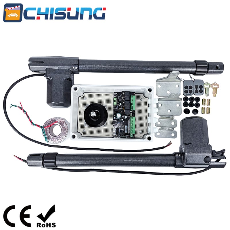
This particular model is a robust system designed for residential use, capable of automating either a single or dual-leaf gate. At its heart is a DC24V motor paired with a worm gear, a combination known for its reliability, quiet operation and inherent braking ability. The worm gear mechanism means the motor is self-locking when not in use, preventing the gate from being pushed open manually without first using the manual release.
Key performance specifications include a peak thrust of 3500N and a nominal thrust of 3000N, with a stroke length of 300mm. This power allows it to handle gates up to 500kg per leaf and up to 4 meters in length, making it suitable for a wide range of residential properties. The system operates on a 20% duty cycle, meaning it is designed for intermittent use typical of a home driveway, not continuous commercial operation.
An important note in the application description clarifies the use of backup batteries. While the system can accommodate them, they are strictly intended for emergency operation during a power failure. For standard, day-to-day use, the system must be powered by the main electricity supply. In the event of a power cut or for manual operation, the gear motors are equipped with a mechanical release that can be activated using special keys, allowing the gate to be moved freely by hand.
Preparing for Installation: A Critical Phase
The installation process is methodical and begins long before the motor is mounted. After planning the cable conduit layout to protect all wiring, the installer must carefully measure the gate and its surroundings. A key part of the preparation is understanding the physical dimensions of the motor and the space required for its operation.
A crucial consideration is the gate's opening direction. If the gate opens outward, the manual specifies a minimum clearance of 70mm between the gate's hinges and the post brackets to accommodate the motor arm's geometry. Furthermore, installers must ensure that when the gate is fully open, it does not encroach on public walkways or collide with any obstacles.
To guarantee smooth operation, the manual provides a formula for determining the correct mounting positions. The relationship between the distance from the gate's hinge pin to the motor's front bracket attachment point (dimension "D"), and the distance from the hinge pin to the mounting post (dimension "C"), is critical. By calculating "A" (A = C + D) and determining the corresponding value for "B" based on the gate's intended opening angle, the installer can establish the ideal geometry. Ensuring dimensions "A" and "B" are proportionally correct is vital for reducing the burden on the motor and ensuring the gate leaf moves smoothly through its entire arc.
Step-by-Step Motor Installation
With the calculations complete, the physical installation can proceed in a structured sequence:
1.Mounting the Brackets: The process starts by assembling and securely fastening the post brackets to the mounting surface (e.g., a brick pillar). This requires drilling holes (minimum 8mm diameter) and using appropriate screws and washers to ensure a rigid, vibration-free mount. The rear plate, which will support the motor's base, is positioned according to the pre-calculated dimension "B" and temporarily fixed. The front plate, which will attach to the moving gate leaf, must be installed in a perfectly horizontal orientation.
2.Attaching the Motor: The front plate of the motor is first clamped temporarily to the gate to verify the positioning. The motor is then lifted, and its front end is secured to this front plate. The installer then needs to release the internal mechanism of the gear motor (as detailed in the manual) to allow the internal piston to be extended or retracted. This allows the rear end of the motor to be aligned with the pre-mounted rear plate on the post.
3.Finalizing the Mount: Once the motor's rear mounting hole aligns with the hole on the rear plate, the bolt is inserted and fastened. A specific detail here is to then loosen the nut by half a turn. This provides a slight amount of rotational play, which is essential for allowing the motor to self-align as the gate moves through its arc, preventing undue stress on the mechanical components. Finally, all connections at the front plate are fully tightened.
4.Electrical Connections and Final Checks: The motor's power cable is connected according to the wiring diagram, typically by a qualified electrician who ensures the circuit includes both short-circuit and leakage protection. Once the electrical work is done, the motor's protective cover is securely closed. A final, critical step is testing the manual release mechanism to ensure the gate can be disengaged and operated by hand in an emergency.
In conclusion, automating a swing gate with a DC24V opener is a project that blends careful mechanical installation with strict electrical safety. From the initial safety checks and precise measurements to the final torqueing of bolts and testing of the manual release, each step is interdependent. For the qualified installer, following the manual is the roadmap to a successful, safe, and durable installation. For the homeowner, understanding this process highlights the importance of entrusting such work to professionals who prioritize safety and precision.
 Hot News
2026-03-11
Copyright © 2026 Chisung Intelligence Technology (Shenzhen) Co., Limited All rights reserved. - Privacy policy